Pipeline ancillaries
Sight glasses
130 95
120 48.5 46.7 10
3.5 2
150 95
140 51 46.7 10
4.3 2
160 95
155 68.5 60.8 15
6.4 3.5
- 150
- 91.5 71.4 15
- 7
180 -
- 72 60.8 15
7.8 -
- 150
202 91.5 71.4 20
- 6.75
200 -
- 86.5 71.4 20
10.5 -
230 150
232 91.5 71.4 20
12.5 6
290 -
- 126.5 113.2 30
27.7 -
310 -
- 134 113.2 30
31 -
350 -
- 143 113.2 30
37 -
7.9.13
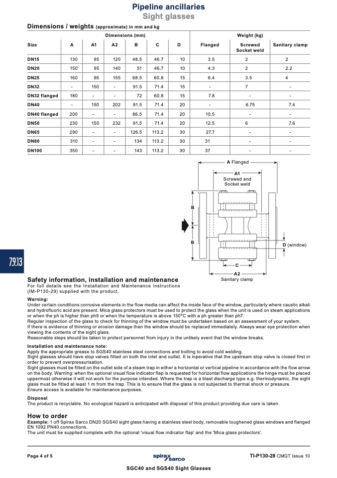
Dimensions / weights (approximate) in mm and kg
Dimensions (mm)
Weight (kg)
Screwed
Socket weld
Size
DN15
DN20
DN25
DN32
DN32
DN40
DN40
DN50
DN65
DN80
DN100
A
A1
A2
B
C
D
Flanged
Sanitary clamp
2
2.2
4
-
-
7.4
-
7.6
-
-
-
flanged
flanged
A Flanged
A1
Screwed and
Socket weld
B
B
D (window)
Safety information, installation and maintenance
For full details see the Installation and Maintenance Instructions
(IM-P130-29) supplied with the product.
Warning:
C
A2
Sanitary clamp
Under certain conditions corrosive elements in the flow media can affect the inside face of the window, particularly where caustic alkali
and hydrofluoric acid are present. Mica glass protectors must be used to protect the glass when the unit is used on steam applications
or when the ph is higher than ph9 or when the temperature is above 150°C with a ph greater than ph7.
Regular inspection of the glass to check for thinning of the window must be undertaken based on an assessment of your system.
If there is evidence of thinning or erosion damage then the window should be replaced immediately. Always wear eye protection when
viewing the contents of the sight glass.
Reasonable steps should be taken to protect personnel from injury in the unlikely event that the window breaks.
Installation and maintenance note:
Apply the appropriate grease to SGS40 stainless steel connections and bolting to avoid cold welding.
Sight glasses should have stop valves fitted on both the inlet and outlet. It is inperative that the upstream stop valve is closed first in
order to prevent overpressurisation.
Sight glasses must be fitted on the outlet side of a steam trap in either a horizontal or vertical pipeline in accordance with the flow arrow
on the body. Warning: when the optional visual flow indicator flap is requested for horizontal flow applications the hinge must be placed
uppermost otherwise it will not work for the purpose intended. Where the trap is a blast discharge type e.g. thermodynamic, the sight
glass must be fitted at least 1 m from the trap. This is to ensure that the glass is not subjected to thermal shock or pressure.
Ensure access is available for maintenance purposes.
Disposal
The product is recyclable. No ecological hazard is anticipated with disposal of this product providing due care is taken.
How to order
Example: 1 off Spirax Sarco DN20 SGS40 sight glass having a stainless steel body, removable toughened glass windows and flanged
EN 1092 PN40 connections.
The unit must be supplied complete with the optional 'visual flow indicator flap' and the 'Mica glass protectors'.
Page 4 of 5
TI-P130-28 CMGT Issue 10
SGC40 and SGS40 Sight Glasses

