7.6.29
WCV1
WCV2
and
WCV3
(DN125 - DN300)
(DN125 - DN300)
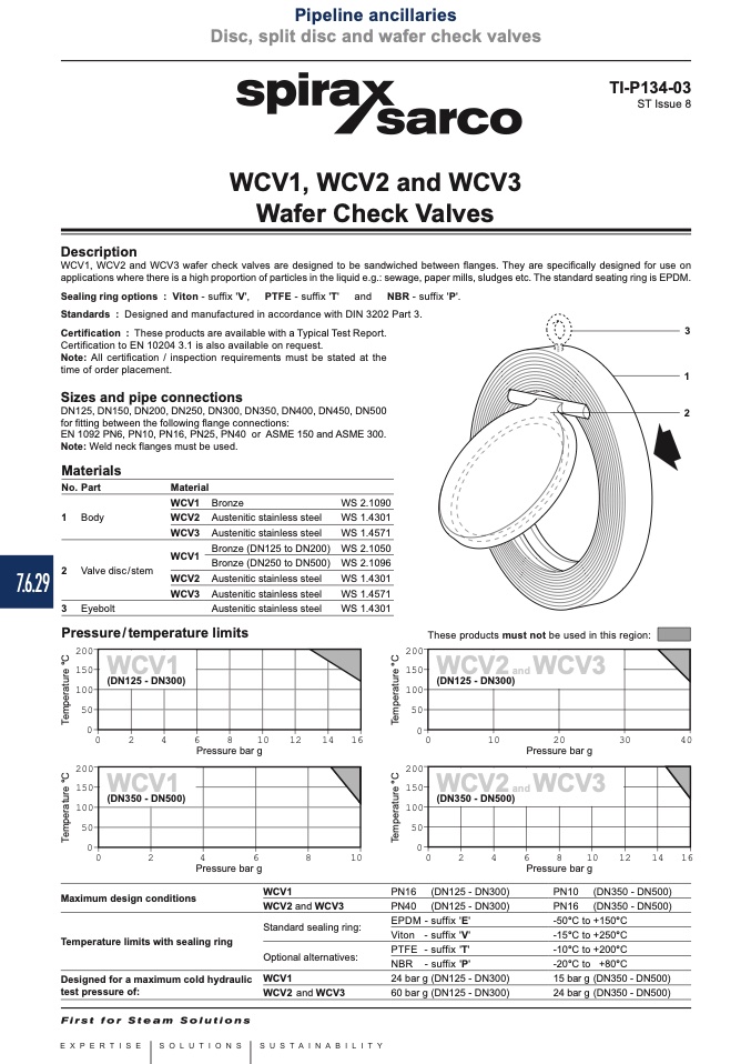
WCV1
WCV2
and
WCV
(DN350 - DN500)
3
(DN350 - DN500)
Pipeline ancillaries
Disc, split disc and wafer check valves
Local regulations may restrict the use of this product to below the conditions quoted.
In the interests of development and improvement of the product, we reserve the right to change the specification without notice.
© Copyright 2015
TI-P134-03
ST Issue 8
Description
WCV1, WCV2 and WCV3
Wafer Check Valves
WCV1, WCV2 and WCV3 wafer check valves are designed to be sandwiched between flanges. They are specifically designed for use on
applications where there is a high proportion of particles in the liquid e.g.: sewage, paper mills, sludges etc. The standard seating ring is EPDM.
Sealing ring options : Viton - suffix 'V', PTFE - suffix 'T' and NBR - suffix 'P'.
Standards : Designed and manufactured in accordance with DIN 3202 Part 3.
Certification : These products are available with a Typical Test Report.
Certification to EN 10204 3.1 is also available on request.
Note: All certification / inspection requirements must be stated at the
time of order placement.
Sizes and pipe connections
DN125, DN150, DN200, DN250, DN300, DN350, DN400, DN450, DN500
for fitting between the following flange connections:
EN 1092 PN6, PN10, PN16, PN25, PN40 or ASME 150 and ASME 300.
Note: Weld neck flanges must be used.
3
1
2
Materials
No. Part
Material
1 Body
2 Valve disc/stem
3 Eyebolt
WCV1
WCV2
WCV3
WCV1
WCV2
WCV3
Bronze
Austenitic stainless steel
Austenitic stainless steel
Bronze (DN125 to DN200)
Bronze (DN250 to DN500)
Austenitic stainless steel
Austenitic stainless steel
Austenitic stainless steel
WS 2.1090
WS 1.4301
WS 1.4571
WS 2.1050
WS 2.1096
WS 1.4301
WS 1.4571
WS 1.4301
150
100
50
Pressure/temperature limits
200
150
100
50
0
0
2
4
6
8
1
0
1
2
14
These products must not be used in this region:
200
200
150
100
50
Pressure bar g
16
0
0
10
20
30
40
Pressure bar g
200
150
100
50
0
0
2
4
6
8
10 12 14 16
Pressure bar g
PN10 (DN350 - DN500)
PN16 (DN350 - DN500)
-50°C to +150°C
-15°C to +250°C
-10°C to +200°C
-20°C to +80°C
15barg (DN350 - DN500)
24barg (DN350 - DN500)
0
0
2
4
6
8
10
Pressure bar g
Maximum design conditions
Temperature limits with sealing ring
Designed for a maximum cold hydraulic
test pressure of:
WCV1
PN16
WCV2 and WCV3
PN40
(DN125 - DN300)
(DN125 - DN300)
suffix 'E'
suffix 'V'
suffix 'T'
suffix 'P'
(DN125 - DN300)
(DN125 - DN300)
Standard sealing ring:
Optional alternatives:
WCV1
WCV2 and WCV3
EPDM -
Viton -
PTFE -
NBR -
24 bar g
60 bar g
T
e
m
p
e
r
a
t
u
r
e
°
C
T
e
m
p
e
r
a
t
u
r
e
°
C
T
e
m
p
e
r
a
t
u
r
e
°
C
T
e
m
p
e
r
a
t
u
r
e
°
C

