The DCV10 and DCV10C are opened by the pressure and flow
of condensate and are closed by the pressure of the spring when
the flow ceases and before reverse flow occurs.
Pipeline ancillaries
Disc, split disc and wafer check valves
Principle of operation
Open
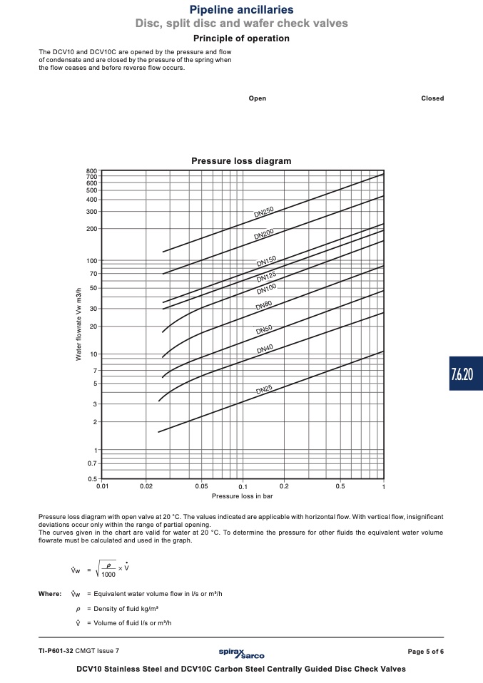
Pressure loss diagram
Closed
������
������
������
������
������
������
������
������
����
����
����
����
����
��
��
��
��
��
������
������
��������
��������
��������
������
Pressure loss in bar
������
������
��
7.6.20
Pressure loss diagram with open valve at 20 °C. The values indicated are applicable with horizontal flow. With vertical flow, insignificant
deviations occur only within the range of partial opening.
The curves given in the chart are valid for water at 20 °C. To determine the pressure for other fluids the equivalent water volume
flowrate must be calculated and used in the graph.
ρ
•
1000
× V
Where:
w = Equivalent water volume flow in l/s or m3/h
= Density of fluid kg/m3
= Volume of fluid l/s or m3/h
TI-P601-32 CMGT Issue 7
DCV10 Stainless Steel and DCV10C Carbon Steel Centrally Guided Disc Check Valves
w
=
Page 5 of 6
����������
����������
����������
����������
����������
W
a
t
e
r
f
l
o
w
r
a
t
e
V
w
m
3
/
h
��������
��������
��������
��������

