Pipeline ancillaries
Disc, split disc and wafer check valves
Dimensions/weights (approximate) in mm and kg
Size
DN15
DN20
DN25
DN32
DN40
DN50
DN65
DN80
DN100 184.0 154
A
B
C
D
E
F
Weight
60.0
43
69.5
53
80.5
63
90.5
75
38 16.0
29.0
15
0.13
45 19.0
35.7
20
0.19
55 22.0
44.0
25
0.32
68 28.0
54.5
32
0.55
101.0
85
115.0
95
142.0 115
154.0 133
0.74
93 40.0
77.0
50
1.25
113 46.0
97.5
65
1.87
128 50.0 111.5
80
2.42
148 60.0 130.0 100
3.81
A
79 31.5
65.5
40
Kv values
DN
15
20
25
32
Kv
4.4
6.8 10.8 17
40
50
65
80 100
26
43
60
80
113
For conversion: Cv (UK) = Kv x 0.963
Cv (US) = Kv x 1.156
Opening pressures in mbar
Differential pressures with zero flow for standard and high
temperature springs.
è Flow direction
DN
15
20
25
32
40
50
65 80 100
25
25
25
27
28
29
30 31 33
è
22.5 22.5 22.5 23.5 24.5 24.5 25 25.5 26.5
20
20
20
20
20
20
20 20 20
Where lowest opening pressures are required, valves without
springs can be installed in vertical pipes with bottom-to-top flow.
B
E
F
D
Without spring
2.5
2.5 2.5 3.5 4.0 4.5
Heavy duty springs approximately 700 mbar
5
5.5
6.5
����
����
����
����
��
��
��
��
������
������
������
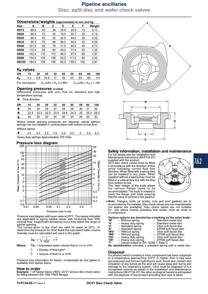
Pressure loss diagram
C
Safety information, installation and maintenance
For full details see the Installation and
Maintenance Instructions (IM-P134-07)
supplied with the product.
DCV disc check valves must be fitted
*
in accordance with the direction of flow
������
������
����
����
����
����
����
��
��
��
��
arrow indicating correct fluid flow
direction. When fitted with a spring they
can be installed in any plane. When
supplied without a spring they must be
fitted in a vertical flow line with the flow
from bottom-to-top.
The 'cam' design of the body allows
the various flange types to be
accommodated. The body is rotated to
touch the flange joint bolts ensuring
that the valve is centred in the pipeline.
*
��
������
������
��������
��������
������
������
������
��
*Note:
Flanges, bolts (or studs), nuts and joint gaskets are to
be provided by the installer. Disc check valves are non-maintainable
(no spares are available). Disc check valves are not suitable
for use where heavily pulsating flow exists, such as close to
a compressor.
��������
Where: Vw
V = Volume of fluid l/s or m3/h
Pressure loss in bar
Pressure loss diagram with open valve at 20°C. The values indicated
are applicable to spring loaded valves with horizontal flow. With
vertical flow, insignificant deviations occur only within the range of
partial opening.
Various options are denoted by a marking on the valve body:-
The curves given in the chart are valid for water at 20°C. To
determine the pressure for other fluids the equivalent water volume
flowrate must be calculated and used in the graph.
Vw =
1000
x V
– Standardmetaldisc
– Standard metal disc
– Viton soft faced disc
– EPDM soft faced disc
– Viton soft faced disc
– EPDM soft faced disc
– Viton soft faced disc
– EPDMsoftfaceddisc
'W'
– Without spring
'H'
– Heavy duty spring
'V'
– Standard spring
'E'
– Standard spring
'WV' – Without spring
'WE' – Without spring
'HV' – Heavy duty spring
'HE' – Heavy duty spring
'T'
– Valves tested to EN 12266-1 Rate D
No identification indicates a standard spring with a metal disc.
Disposal
If a product which contains a Viton component has been subjected
to a temperature approaching 315°C or higher, then it may have
decomposed and formed hydrofluoric acid. Avoid skin contact and
inhalation of any fumes as the acid will cause deep skin burns and
damage to the respiratory system. Viton must be disposed of in a
recognised manner as stated in the Installation and Maintenance
Instructions (IM-P134-07). No other ecological hazard is anticipated
with the disposal of this product providing due care is taken.
= Equivalent water volume flow in l/s or m3/h
= Density of fluid kg/m3
Pressure loss information for steam, compressed air and gases is
available from Spirax Sarco.
How to order
Example: 1 off Spirax Sarco DN50, DCV1 bronze disc check valve
for fitting between EN 1092 PN25 flanges.
TI-P134-05 ST Issue 9
DCV1 Disc Check Valve
7.6.2
����������
��������
��������
��������
��������
��������
��������
��������
��������
e
̀
W
a
t
e
r
f
l
o
w
r
a
t
e
i
n
V
w
I
/
s
W
a
t
e
r
f
l
o
w
r
a
t
e
i
n
V
w
m
3
/
h
e
̀
e
̀

