Pipeline ancillaries
Local regulations may restrict the use of this product to below the conditions quoted.
HVB3aslltvoaplveaslve
In the interests of development and improvement of the product, we reserve the right to change the specification without notice. © Copyright 2016
TI-P133-81
ST Issue 4
M21Fi ISO
Reduced Bore Firesafe API607 Ball Valve
DN15 to DN150 Flanged PN40
Description
The M21Fi is a reduced bore ball valve, with a single piece body,
having ISO mounting as standard. It is designed to be an isolating
valve, which can be used with the majority of industrial fluids, not
a control valve.
Firesafe design
In normal working conditions, the ball rests against two PDR 0.8
seats ensuring total closure. When the valve is submitted to
temperature above the limits the seats can withstand, the seat
becomes deformed and renders to extrusion. When the seats have
been totally destroyed, the ball will come to rest firmly against the
metal seat in the cap, producing a metal-to-metal closing. This
secondary seat in the valve cap ensures the valve will operate to
international API 607 standard.
Available types
M21Fi2 ISO
Zinc plated carbon steel body, PDR 0.8 seats.
M21Fi3 ISO
Stainless steel body, PDR 0.8 seats.
Standards
This product fully complies with the requirements of the European
Pressure Equipment Directive 97/23/EC and carries the
mark when so required.
Certification
This product is available with certification to EN 10204 3.1.
Note: All certification / inspection requirements must be stated at
the time of order placement.
Pressure / temperature limits
������
������
������
������
����
��
������
Sizes and pipe connections
DN15, DN20, DN25, DN32, DN40, DN50, DN65, DN80, DN100
and DN150
Standard flange: EN 1092 PN40
Face-to-face dimensions:
-
DN15 to DN100 according to DIN 3202 F4.
-
DN25 to DN150 according to BS 2080.
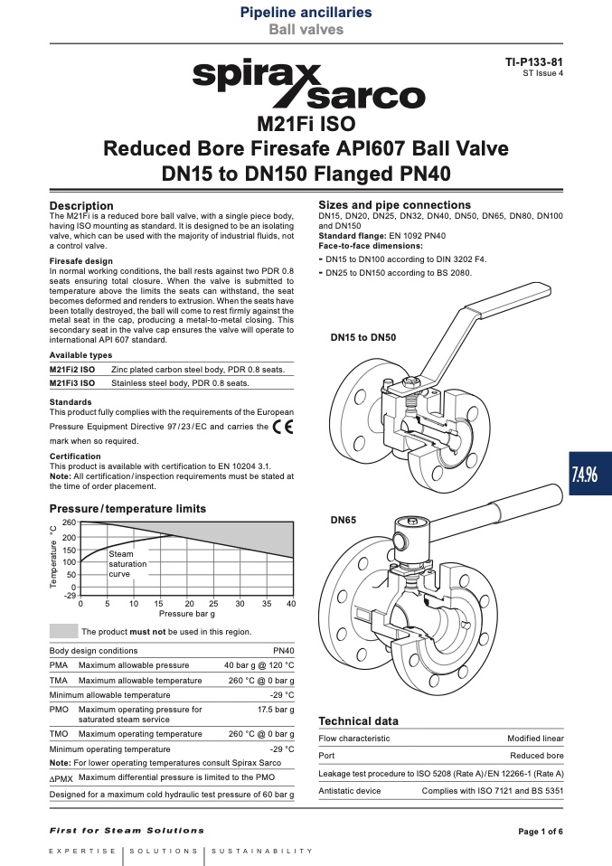
DN15 to DN50
Steam
saturation
curve
DN65
��
��
����
����
����
����
����
����
����
Pressure bar g
The product must not be used in this region.
Body design conditions
PMA Maximum allowable pressure
TMA Maximum allowable temperature
Minimum allowable temperature
PMO Maximum operating pressure for
saturated steam service
TMO Maximum operating temperature
Minimum operating temperature
Note: For lower operating temperatures consult Spirax Sarco
PMX MaximumdifferentialpressureislimitedtothePMO
Designed for a maximum cold hydraulic test pressure of 60 bar g
PN40
40 bar g @ 120 °C
260 °C @ 0 bar g
-29 °C
17.5 bar g
260 °C @ 0 bar g
Technical data
Flow characteristic
Port
Modified linear
Reduced bore
-29 °C
Leakage test procedure to ISO 5208 (Rate A) / EN 12266-1 (Rate A)
Antistatic device
Complies with ISO 7121 and BS 5351
Page 1 of 6
7.4.96
T
e
m
p
e
r
a
t
u
r
e
°
C

