Pipeline ancillaries
HVB3aslltvoaplveaslve
ISO 9001
7.4.53
For liquids
Where:
Sub-critical flow
When:
DP < DPm
Volumetric flowrate
pr
∆P
Cv =
��
865 ∆Ppr
Critical flow
When:
DP > DPm
Volumetric flowrate
Cv =
1.16��
pr
F
L
∆Pm
Mass flowrate
DPm =
Cv =
F
L
=
pr =
P
1
=
P
2
=
P
V
=
Pc =
V =
m=
Maximum DP for sizing,
WhenP
2
>PvuseDPm=F
L
2(P
1
-Pv)
Pv
WhenP
2
≤ PvuseDPm=P
1
- 0.96-0.28
P
Pv
Flow coeffecient of the valve
Pressure recovery factor
Density at inlet temperature (water = 1.0 at STP)
Upstream pressure (bar a)
Downstream presure (bar a)
Vapour pressure of the liquid at inlet temperature (bar a)
Thermodynamic critical pressure (bar a)
Flowrate in m3/h
Flowrate in in kg/h
c
Cv = 1.16��
Mass flowrate
Cv =
��
865 F
L
pr∆Pm
TI-P133-46
ST Issue 1
Cert. No. LRQ 110478
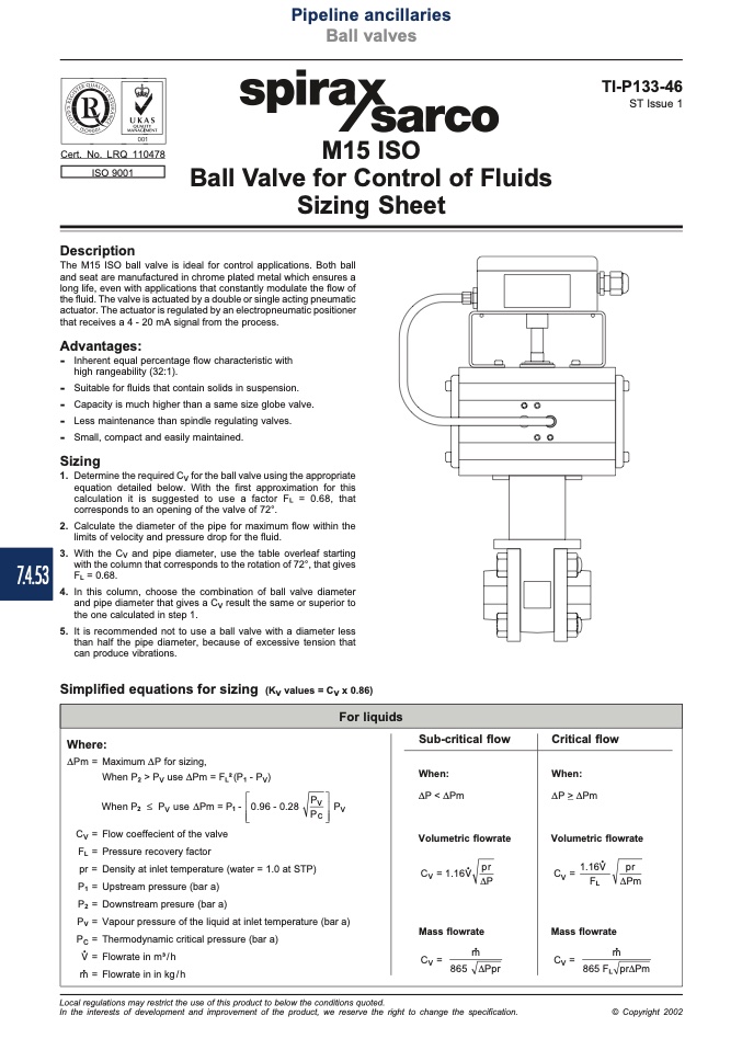
Description
M15 ISO
Ball Valve for Control of Fluids
Sizing Sheet
The M15 ISO ball valve is ideal for control applications. Both ball
and seat are manufactured in chrome plated metal which ensures a
long life, even with applications that constantly modulate the flow of
the fluid. The valve is actuated by a double or single acting pneumatic
actuator. The actuator is regulated by an electropneumatic positioner
that receives a 4 - 20 mA signal from the process.
Advantages:
-
Inherentequalpercentageflowcharacteristicwith
high rangeability (32:1).
-
Suitableforfluidsthatcontainsolidsinsuspension.
-
Capacityismuchhigherthanasamesizeglobevalve.
-
Lessmaintenancethanspindleregulatingvalves.
-
Small,compactandeasilymaintained.
Sizing
1. DeterminetherequiredCvfortheballvalveusingtheappropriate
equation detailed below. With the first approximation for this
calculation it is suggested to use a factor F
L
= 0.68, that
corresponds to an opening of the valve of 72°.
2. Calculate the diameter of the pipe for maximum flow within the
limits of velocity and pressure drop for the fluid.
3. With the Cv and pipe diameter, use the table overleaf starting
with the column that corresponds to the rotation of 72°, that gives
F
L
= 0.68.
4. In this column, choose the combination of ball valve diameter
and pipe diameter that gives a Cv result the same or superior to
the one calculated in step 1.
5. It is recommended not to use a ball valve with a diameter less
than half the pipe diameter, because of excessive tension that
can produce vibrations.
Simplified equations for sizing (Kv values = Cv x 0.86)
Local regulations may restrict the use of this product to below the conditions quoted.
In the interests of development and improvement of the product, we reserve the right to change the specification.
© Copyright 2002

