7.2.1
Steam
saturation
curve
Pipeline ancillaries
HV3 stop valve
Local regulations may restrict the use of this product to below the conditions quoted.
In the interests of development and improvement of the product, we reserve the right to change the specification without notice.
© Copyright 2012
TI-P060-01
ST Issue 7
HV3
Stop Valve
Description
A bronze bodied globe valve for steam, water, oil or air applications.
To BS 5154 Series A.
Sizes and pipe connections
1⁄2", 3⁄4", 1", 11⁄4",11⁄2" and 2" screwed BSP parallel.
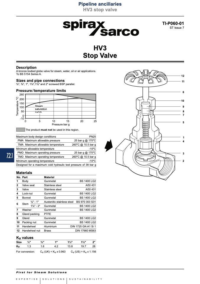
Pressure/temperature limits
������
������
������
������
����
��
������
The product must not be used in this region.
Maximum body design conditions
12
11
6
10
9
8
7
5
1
4
3
2
��
��
����
����
����
����
Pressure bar g
PN25
25 bar g @ 170°C
260°C @ 10.5 bar g
-10°C
25 bar g @ 170°C
260°C @ 10.5 bar g
-10°C
Designed for a maximum cold hydraulic test pressure of 38 bar g
PMA Maximum allowable pressure
TMA Maximum allowable temperature
Minimum allowable temperature
PMO Maximum operating pressure
TMO Maximum operating temperature
Minimum operating temperature
Materials
No. Part
1 Body
2 Valve seat
3 Valve
4 Lock-nut
5 Bonnet
6 Stem
1⁄2" - 1"
11⁄4" - 2"
7 Washer
8 Gland packing
9 Gland
10 Packing nut
11 Handwheel
12 Handwheel nut
Material
Gunmetal
Stainless steel
Stainless steel
Gunmetal
Gunmetal
Austenitic
Gunmetal
Gunmetal
PTFE
Gunmetal
Gunmetal
Aluminium
Brass
BS 1400 LG2
AISI 431
AISI 431
BS 1400 LG2
BS 1400 LG2
BS 970 303 S31
BS 1400 LG2
BS 1400 LG2
BS 1400 LG2
stainless steel
BS 1400 LG2
DIN 1725 GK-A1 Si 1
DIN 17660 MS63
Kv values
Size
1⁄2"
3⁄4"
1"
11⁄4"
11⁄2"
2"
Kv
1.3
1.6
4.2
13.8
19.7
28
For conversion:
Cv (UK) = Kv x 0.963
Cv (US) = Kv x 1.156
T
e
m
p
e
r
a
t
u
r
e
°
C

