Condensate pumps
Mechanical pumps and pumps traps
Page 4 of 6
Plant
1500 kg/h
Reservoir
Filling head
metres (m)
Capacity multiplying factors
DN25
DN40
DN50
DN80 x DN50
0.15
0.90
0.75
0.75
0.80
0.30
1.00
1.00
1.00
1.00
0.60
1.15
1.10
1.20
1.05
0.90
1.35
1.25
1.30
1.15
6.1.17
Pump
size
% Backpressure Vs Motive pressure (BP/MP)
10%
20%
30%
40%
50%
60%
70%
80%
90%
Capacity multiplying factors
DN25
1.20
1.25
1.30
1.35
1.40
1.43
1.46
1.50
1.53
DN40
1.20
1.25
1.30
1.35
1.40
1.43
1.46
1.50
1.53
DN50
1.02
1.05
1.08
1.10
1.15
1.20
1.27
1.33
1.40
DN80 x DN50
1.02
1.05
1.08
1.10
1.15
1.20
1.27
1.33
1.40
How to size and select
Considering the inlet pressure, backpressure and filling head
conditions, select the pump size which meets the capacity
requirements of the application.
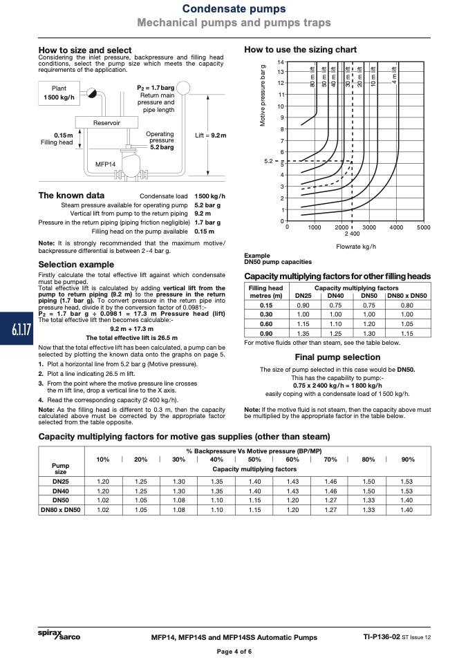
How to use the sizing chart
P
2
= 1.7barg
Return main
pressure and
pipe length
Operating
pressure
5.2 barg
Condensate load
Steam pressure available for operating pump
Vertical lift from pump to the return piping
Pressure in the return piping (piping friction negligible)
Filling head on the pump available
Lift = 9.2m
1500kg/h
5.2 bar g
9.2 m
1.7 bar g
0.15 m
��
��
��
��
��
�
�
�
�
���
�
�
�
�
�
�
Example
DN50 pump capacities
0.15 m
Filling head
MFP14
The known data
Note: It is strongly recommended that the maximum motive/
backpressure differential is between 2-4 bar g.
Selection example
Firstly calculate the total effective lift against which condensate
must be pumped.
Total effective lift is calculated by adding vertical lift from the
pump to return piping (9.2 m) to the pressure in the return
piping (1.7 bar g). To convert pressure in the return pipe into
pressure head, divide it by the conversion factor of 0.0981:-
P
2
= 1.7 bar g ÷ 0.0981 = 17.3 m Pressure head (lift)
The total effective lift then becomes calculable:-
9.2 m + 17.3 m
The total effective lift is 26.5 m
Now that the total effective lift has been calculated, a pump can be
selected by plotting the known data onto the graphs on page 5.
1. Plot a horizontal line from 5.2 bar g (Motive pressure).
2. Plot a line indicating 26.5 m lift.
3. Fromthepointwherethemotivepressurelinecrosses
the m lift line, drop a vertical line to the X axis.
4. Read the corresponding capacity (2 400 kg / h).
Note: As the filling head is different to 0.3 m, then the capacity
calculated above must be corrected by the appropriate factor
selected from the table opposite.
Capacity multiplying factors for other filling heads
For motive fluids other than steam, see the table below.
Final pump selection
The size of pump selected in this case would be DN50.
This has the capability to pump:-
0.75 x 2400 kg/h = 1800 kg/h
easily coping with a condensate load of 1500 kg/h.
Note: If the motive fluid is not steam, then the capacity above must
be multiplied by the appropriate factor in the table below.
�
����
����
����
����
����
�����
Flowrate kg/h
Capacity multiplying factors for motive gas supplies (other than steam)
MFP14, MFP14S and MFP14SS Automatic Pumps
TI-P136-02 ST Issue 12
Page 4 of 6
M
o
t
i
v
e
p
r
e
s
s
u
r
e
b
a
r
g
�
�
�
�
�
�
�
�
�
�
�
�
�
�
�
�
�
�
�
�
�
�
�
�
�
�
�
�
�
�
�
�
�
�
�
�
�
�
�
�
�
�
�
�
�
�
�
�
�
�
�
�
�
�
�
�
�
�
�
�
�
�

