Type
PC43
PC44
PC40
PC45
PC46
PC47
5.9.15
Steam
saturation
curve
The product
must not be
used in this
region.
Steam traps
Swivel connectors and traps
Local regulations may restrict the use of this product to below the conditions quoted.
In the interests of development and improvement of the product, we reserve the right to change the specification without notice.
© Copyright 2013
TI-P128-03
ST Issue 8
PC4_
Pipeline Connectors
Description
The PC4_ range of pipeline connectors have been designed for
use with swivel connector steam traps. The PC4_ is a pipeline
connector with two integral stop valves which isolate upstream
and downstream of the steam trap. The stop valves are piston
type. The PC4_ is available with optional connections (BDV1
and/or BDV2) for the draining of upstream pipework and trap
venting upstream and trap testing downstream of the steam trap
- See 'Optional extras'.
Optional extras (see TI-P600-01 for further details)
BDV1 blowdown valve is available for the draining of upstream
pipework and trap testing downstream of the steam trap during
operation. Care should be taken when using the BDV1 blowdown
valve as the discharge may be hot.
BDV2 depressurisation valve is available to provide side
connection discharge, generally to be used as a vent for top pipe
mounting or for line depressurisation, to ensure discharge is piped
to grade/atmosphere.
These products fully comply with the requirements of the
European Pressure Equipment Directive 97 / 23 / EC.
Certification
These products are available with certification to EN 10204 3.1.
Note: All certification/inspection requirements must be stated
at the time of order placement. For other certification contact
Spirax Sarco.
DN15 and DN20 condensate inlet/outlet connections are
available in screwed BSP or NPT and socket weld ends to
ASME B16.11 class 3000. Drainage and venting connections are
available in DN15 screwed BSP or NPT and socket weld
connections for use with BDV1 or BDV2 valves.
Flanged versions are also available upon request. Please contact
Spirax Sarco for further details.
Pressure/temperature limits
������
������
������
������
������
��
�
�
���
�
���
�
���
�
���
�
��������
Pressure bar g
Available types
For piping installation diagrams see TI-F01-37.
Flow direction
Left to right
Right to left
Description
2 stop valves + upstream line drain and
trap vent connections + dowstream trap
test connections for: BDV1 or BDV2
2 stop valves
2 stop valves +
upstream line drain connection either
side of the body for: BDV1 or BDV2.
It is necessary to plug one connection.
This must always be the top connection.
2 stop valves + upstream line drain
connection + dowstream trap test
connections for: BDV1 or BDV2
Universal -
Both:
left to right
or
right to left
Left to right
Right to left
11 12
1
Standards
Sizes and pipe connections
10
9
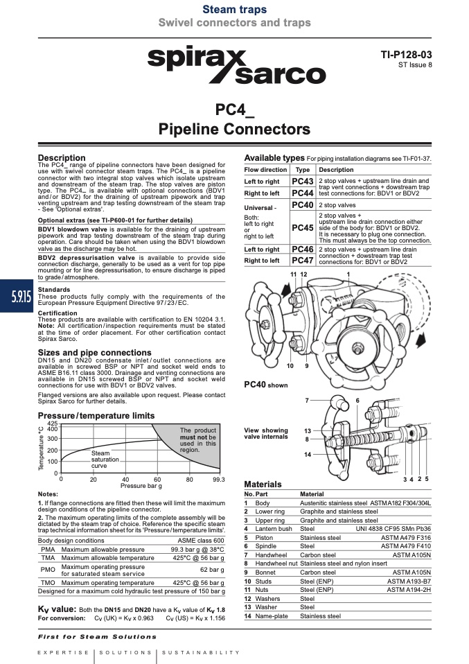
PC40 shown
View showing
valve internals
Materials
No. Part
1 Body
2 Lower ring
3 Upper ring
4 Lantern bush
5 Piston
6 Spindle
7 Handwheel
8 Handwheel nut
9 Bonnet
10 Studs
11 Nuts
12 Washers
13 Washer
14 Name-plate
7
6
13
8
14
Material
3425
Notes:
1. If flange connections are fitted then these will limit the maximum
Austenitic stainless steel ASTM A182 F304/304L
Graphite and stainless steel
Graphite and stainless steel
design conditions of the pipeline connector.
2. The maximum operating limits of the complete assembly will be
dictated by the steam trap of choice. Reference the specific steam
trap technical information sheet for its 'Pressure / temperature limits'.
Steel
Stainless steel
Steel
Carbon steel
Stainless steel and nylon insert
Carbon steel
Steel (ENP)
Steel (ENP)
Steel
Steel
Stainless steel
Body design conditions
PMA Maximum allowable pressure
TMA Maximum allowable temperature
PMO
Maximum operating pressure
for saturated steam service
TMO Maximum operating temperature
ASME class 600
99.3 bar g @ 38°C
425°C @ 56 bar g
62 bar g
UNI 4838 CF95 SMn Pb36
ASTM A479 F316
ASTM A479 F410
ASTM A105N
425°C @ 56 bar g
Designed for a maximum cold hydraulic test pressure of 150 bar g
ASTM A105N
ASTM A193-B7
ASTM A194-2H
Kv value:
Both the DN15 and DN20 have a Kv value of Kv 1.8
For conversion: Cv (UK) = Kv x 0.963
Cv (US) = Kv x 1.156
T
e
m
p
e
r
a
t
u
r
e
°
C

