Insulating cover: To prevent the trap being unduly influenced by
5.7.7
excessive heat loss such as when subjected to low outside
These products fully comply with the requirements of the
European Pressure Equipment Directive 97/23/EC.
These products are available with certification to EN 10204 3.1.
Note: All certification / inspection requirements must be stated
at the time of order placement.
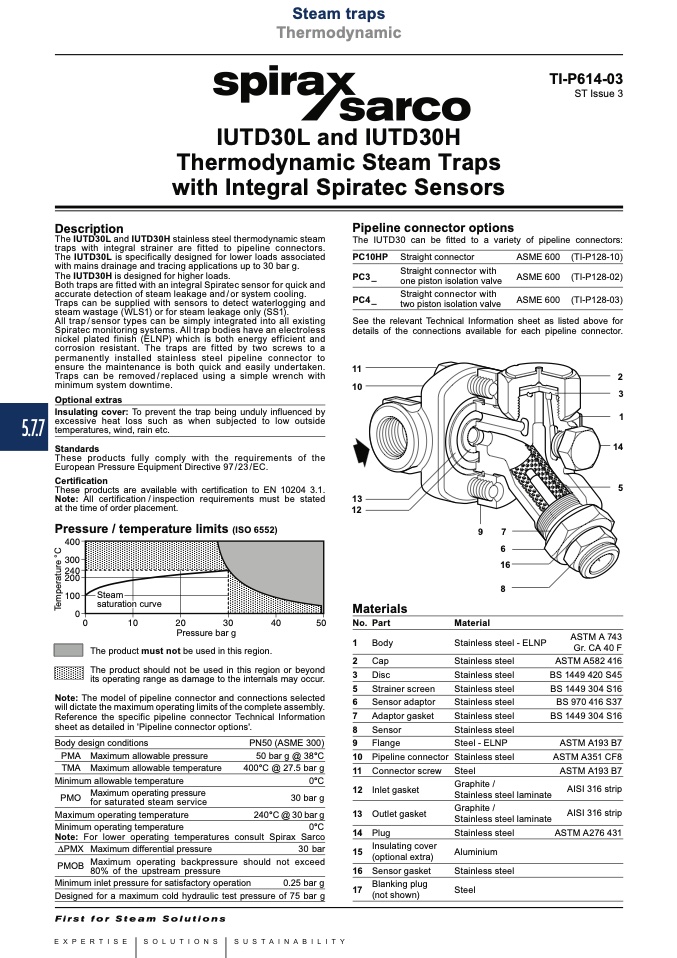
Pressure / temperature limits (ISO 6552)
������
������
������
������
������
��
Note: The model of pipeline connector and connections selected
will dictate the maximum operating limits of the complete assembly.
Reference the specific pipeline connector Technical Information
sheet as detailed in 'Pipeline connector options'.
11
10
13
12
Materials
No. Part
1 Body
2 Cap
3 Disc
5 Strainer screen
6 Sensor adaptor
7 Adaptor gasket
8 Sensor
9 Flange
10 Pipeline connector
11 Connector screw
12 Inlet gasket
13 Outlet gasket
2
3
1
14
5
temperatures, wind, rain etc.
Standards
Certification
Steam
saturation curve
��
����
����
����
����
����
Pressure bar g
9
7
6
16
8
The product must not be used in this region.
The product should not be used in this region or beyond
Stainless steel
Stainless steel
Stainless steel
Stainless steel
Stainless steel
Stainless steel
Stainless steel
Steel - ELNP
Stainless steel
Steel
Graphite /
Stainless steel
Graphite /
Stainless steel
Stainless steel
Aluminium
Stainless steel
Steel
- ELNP
ASTM A 743
Gr. CA 40 F
ASTM A582 416
BS 1449 420 S45
BS 1449 304 S16
BS 970 416 S37
BS 1449 304 S16
ASTM A193 B7
ASTM A351 CF8
ASTM A193 B7
AISI 316 strip
AISI 316 strip
ASTM A276 431
its operating range as damage to the internals may occur.
Body design conditions
PMA Maximum allowable pressure
TMA Maximum allowable temperature
Minimum allowable temperature
PMO
Maximum operating pressure
for saturated steam service
Maximum operating temperature
Minimum operating temperature
PN50 (ASME 300)
50 bar g @ 38°C
400°C @ 27.5 bar g
0°C
30 bar g
240°C @ 30 bar g
laminate
laminate
0°C
Note: For lower operating temperatures consult Spirax Sarco
14 Plug
Insulating cover
PMX Maximum differential pressure
30 bar
PMOB
Maximum operating backpressure should not exceed
15
(optional extra)
80% of the upstream pressure
Minimum inlet pressure for satisfactory operation
0.25 bar g
Designed for a maximum cold hydraulic test pressure of 75 bar g
16 Sensor gasket
17
Blanking plug
(not shown)
Steam traps
Thermodynamic
Local regulations may restrict the use of this product to below the conditions quoted.
In the interests of development and improvement of the product, we reserve the right to change the specification without notice.
© Copyright 2015
IUTD30L and IUTD30H
Thermodynamic Steam Traps
with Integral Spiratec Sensors
Description
The IUTD30L and IUTD30H stainless steel thermodynamic steam
traps with integral strainer are fitted to pipeline connectors.
The IUTD30L is specifically designed for lower loads associated
with mains drainage and tracing applications up to 30 bar g.
The IUTD30H is designed for higher loads.
Both traps are fitted with an integral Spiratec sensor for quick and
accurate detection of steam leakage and / or system cooling.
Traps can be supplied with sensors to detect waterlogging and
steam wastage (WLS1) or for steam leakage only (SS1).
All trap / sensor types can be simply integrated into all existing
Spiratec monitoring systems. All trap bodies have an electroless
nickel plated finish (ELNP) which is both energy efficient and
corrosion resistant. The traps are fitted by two screws to a
permanently installed stainless steel pipeline connector to
ensure the maintenance is both quick and easily undertaken.
Traps can be removed / replaced using a simple wrench with
minimum system downtime.
Optional extras
Pipeline connector options
The IUTD30 can be fitted to a variety of pipeline connectors:
PC10HP
PC3 _
PC4 _
Straight connector
Straight connector with
one piston isolation valve
Straight connector with
two piston isolation valve
ASME 600
ASME 600
ASME 600
(TI-P128-10)
(TI-P128-02)
(TI-P128-03)
See the relevant Technical Information sheet as listed above for
details of the connections available for each pipeline connector.
Material
TI-P614-03
ST Issue 3
T
e
m
p
e
r
a
t
u
r
e
°
C

