5.7.5
Steam
saturation
curve
Steam traps
Thermodynamic
Local regulations may restrict the use of this product to below the conditions quoted.
In the interests of development and improvement of the product, we reserve the right to change the specification without notice.
© Copyright 2015
TI-P068-04
ST Issue 8
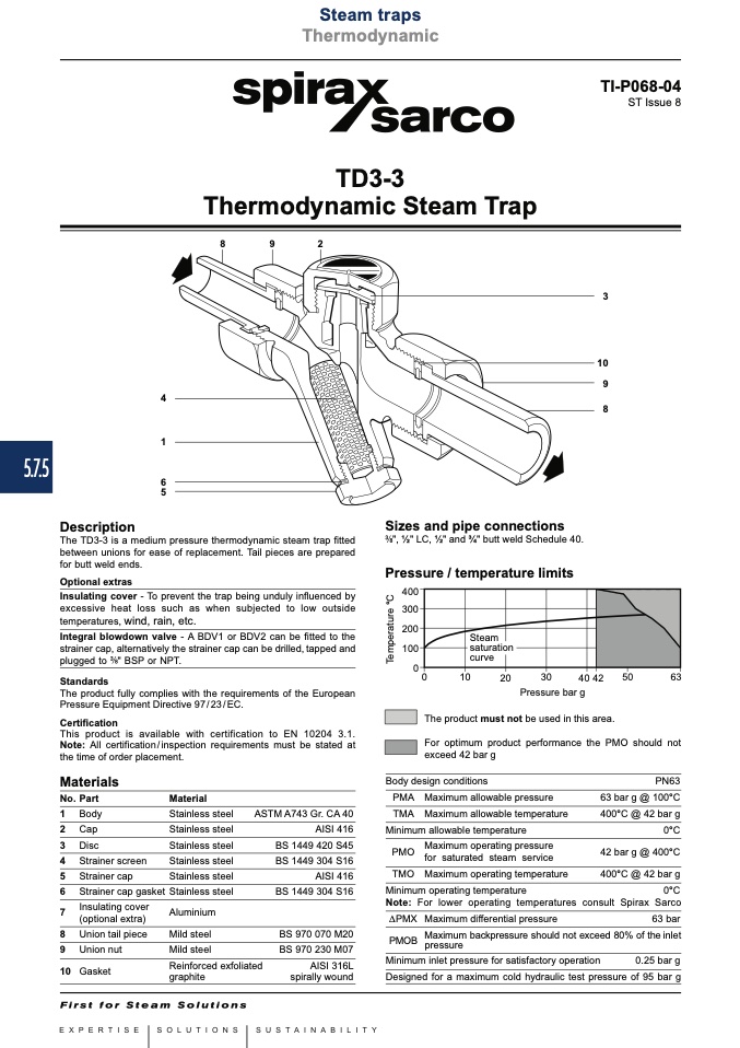
TD3-3
Thermodynamic Steam Trap
8
9
2
4
1
6
5
3
10
9
8
Description
Sizes and pipe connections
", 1⁄2" LC, 1⁄2" and 3⁄4" butt weld Schedule 40.
Pressure / temperature limits
The TD3-3 is a medium pressure thermodynamic steam trap fitted
between unions for ease of replacement. Tail pieces are prepared
for butt weld ends.
Optional extras
Insulating cover - To prevent the trap being unduly influenced by
excessive heat loss such as when subjected to low outside
temperatures, wind, rain, etc.
Integral blowdown valve - A BDV1 or BDV2 can be fitted to the
strainer cap, alternatively the strainer cap can be drilled, tapped and
plugged to " BSP or NPT.
Standards
The product fully complies with the requirements of the European
Pressure Equipment Directive 97/23/EC.
Certification
This product is available with certification to EN 10204 3.1.
Note: All certification/inspection requirements must be stated at
the time of order placement.
������
������
������
������
��
��
����
����
����
��������
����
����
Pressure bar g
The product must not be used in this area.
For optimum product performance the PMO should not
Materials
No. Part
1 Body
2 Cap
3 Disc
4 Strainer screen
5 Strainer cap
6 Strainer cap gasket
7
Insulating cover
(optional extra)
8 Union tail piece
9 Union nut
10 Gasket
Material
Stainless steel
Stainless steel
Stainless steel
Stainless steel
Stainless steel
Stainless steel
Aluminium
Mild steel
Mild steel
Reinforced exfoliated
graphite
Body design conditions
PMA Maximum allowable pressure
TMA Maximum allowable temperature
Minimum allowable temperature
PMO
Maximum operating pressure
for saturated steam service
TMO Maximum operating temperature
Minimum operating temperature
PN63
63 bar g @ 100°C
400°C @ 42 bar g
0°C
42 bar g @ 400°C
400°C @ 42 bar g
exceed 42 bar g
ASTM A743 Gr. CA 40
AISI 416
BS 1449 420 S45
BS 1449 304 S16
AISI 416
BS 1449 304 S16
BS 970 070 M20
BS 970 230 M07
AISI 316L
spirally wound
0°C
Note: For lower operating temperatures consult Spirax Sarco
DPMX Maximum differential pressure
63 bar
PMOB
Maximum backpressure should not exceed 80% of the inlet
pressure
Minimum inlet pressure for satisfactory operation
0.25 bar g
Designed for a maximum cold hydraulic test pressure of 95 bar g
T
e
m
p
e
r
a
t
u
r
e
°
C

