������
������
������
��
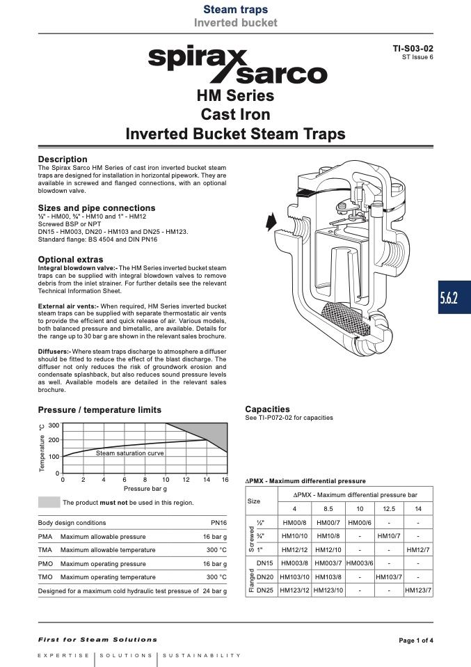
The product must not be used in this region.
Body design conditions
PMA Maximum allowable pressure
TMA Maximum allowable temperature
PMO Maximum operating pressure
TMO Maximum operating temperature
Designed for a maximum cold hydraulic test pressue of
Capacities
See TI-P072-02 for capacities
DPMX - Maximum differential pressure
Steam saturation curve
��
��
��
��
��
����
����
����
����
Pressure bar g
DPMX - Maximum differential pressure bar
Steam traps
Local regulations may restrict the use of this product to below the conditions quoted.
In the interests of development and improvement of the product, we reserve the right to change the specification without notice.
Inverted bucket
© Copyright 2016
HM Series
Cast Iron
Inverted Bucket Steam Traps
Description
The Spirax Sarco HM Series of cast iron inverted bucket steam
traps are designed for installation in horizontal pipework. They are
available in screwed and flanged connections, with an optional
blowdown valve.
Sizes and pipe connections
1⁄2" - HM00, 3⁄4" - HM10 and 1" - HM12
Screwed BSP or NPT
DN15 - HM003, DN20 - HM103 and DN25 - HM123.
Standard flange: BS 4504 and DIN PN16
Optional extras
Integral blowdown valve:- The HM Series inverted bucket steam
traps can be supplied with integral blowdown valves to remove
debris from the inlet strainer. For further details see the relevant
Technical Information Sheet.
External air vents:- When required, HM Series inverted bucket
steam traps can be supplied with separate thermostatic air vents
to provide the efficient and quick release of air. Various models,
both balanced pressure and bimetallic, are available. Details for
the range up to 30 bar g are shown in the relevant sales brochure.
Diffusers:- Where steam traps discharge to atmosphere a diffuser
should be fitted to reduce the effect of the blast discharge. The
diffuser not only reduces the risk of groundwork erosion and
condensate splashback, but also reduces sound pressure levels
as well. Available models are detailed in the relevant sales
brochure.
Pressure / temperature limits
5.6.2
PN16
16 bar g
300 °C
16 bar g
300 °C
24 bar g
4
8.5
10
12.5
14
1⁄2"
HM00/8 HM00/7 HM00/6
-
-
3⁄4"
HM10/10 HM10/8
-
HM10/7
-
1"
HM12/12 HM12/10
-
-
HM12/7
DN15 HM003/8 HM003/7 HM003/6
-
-
DN20 HM103/10 HM103/8
-
HM103/7
-
Size
DN25 HM123/12 HM123/10
-
-
HM123/7
TI-S03-02
ST Issue 6
F
l
a
n
g
e
d
S
c
r
e
w
e
d
T
e
m
p
e
r
a
t
u
r
e
°
C
Page 1 of 4

