4
Liquid-side Pipe
1/4
p
GRS CQ4.0Pd/NhH E(I),GRS CQ6.0Pd/NhH E(I
)
GRS-CQ8.0Pd/NhH-E(I),GRS-CQ10Pd/NhH-E(I
)
4.5.5 Precautions on installation of indoor unit
VERSATI ALL IN ONE
(1) Indoor unit shall be vertically mounted on the wall of the room with expansion bolt.
6-8-10 kW - DATI TECNICI
(2) Keep the indoor unit away from heat sources like heat sink and so on in the room as much as possible.
(3) Keep the indoor unit as close as possible to outdoor unit. Level distance between connection pipe
s
cannotexceed 20m(4.0~6.0kW) or 25m (8.0~10kW) and vertical distance cannot exceed 15m.
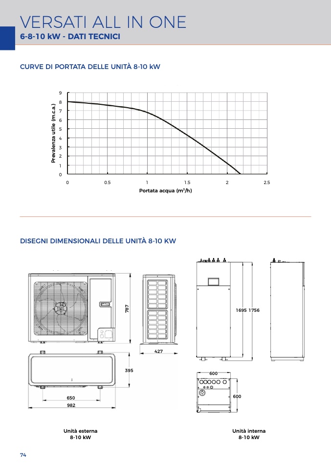
CURVE DI PORTATA DELLE UNITÀ 8-10 kW
4.5.6 Available External Static Pressure of Outle
t
Versati III Split Typ
e
P
r
e
v
a
l
e
n
z
a
u
t
i
l
e
(
m
.
c
.
a
.
)
A
v
a
i
l
a
b
l
e
E
x
t
e
r
n
a
l
S
t
a
t
i
c
P
r
e
s
s
u
r
e
o
f
O
u
t
l
e
t
9
8
7
6
Air-to-water Heat Pump Split Versat
i
Air-to-water Heat Pump Split Versati
4.5.2 Space requirements for installatio
n
4.5.2 Space requirements for installation
5
4
3
2
1
0
0
0.5
1
1.5
2
2.
5
Water Flow
Portata acqua (m3/h)
Wall
Wall
Wal
l
Wall
Wall
Wall
Note: see the curve above for the maximum external static pressure. The water pump is of variable frequency
.
And during operation, the water pump will adjust its output based on the actual load.
DISEGNI DIMENSIONALI DELLE UNITÀ 8-10 KW
8
5
4.5.3 Outline dimension of indoor unit
t
er Heat Pump Split Versati
t
o-water Heat Pump Split Versati
SPLIT TYPE
SPLIT TYP
E
4.5.3 Outline dimension of indoor unit
(
2) GRS-CQ8.0Pd/NhH-E(O), GRS-CQ10Pd/NhH-E(O
)
R
S-CQ8.0Pd/NhH-E(O), GRS-CQ10Pd/NhH-E(O)
7
8
7
1695 1756
1695 175
6
1695 1756
427
395
600
600
600
65
0
600
600
600
982
D
escription
:
p
tion:
Description:
N
o.
Name
Remarks
Name
Remark
s
Description:
1
Liquid-side Service Valve
1/
4
Liquid-side Service Valve
1/
4
Unità estern
a
8-10 k
W
Unità interna
No.
Description
Joint Pipe Threa
d
GRS-CQ4.0Pd/NhH-E,GRS-CQ6.0Pd/NhH-E
GRS-CQ4.0Pd/NhH-E,GRS-CQ6.0Pd/NhH-
E
8-10 k
W
No.
Description
Joint Pipe Thread
GRS-CQ8.0Pd/NhH-E,GRS-CQ10Pd/NhH-E
GRS-CQ8.0Pd/NhH-E,GRS-CQ10Pd/NhH-E
2
Gas-side Service Valve
1/
2
Gas-side Service Valve
1/2
1
Supply water
1″Male BS
P
1
Supply water
1″Male BS
P
2
Return water
1″Male BS
P
74
Handle
3
Handle
Used to cover or uncover the front casew
Used to cover or uncover the front casew
2
Return water
1″Male BS
P
3
Tap water
1″Male BS
P
Air discharge Grill
/
4
Air discharge Grill
/
3
Tap water
1″Male BSP
1
S
600m
m
600m

