GRUPPI DI CIRCOLAZIONE PER BIOMASSA / BIOMASS HEATING GROUPS
Mod. 100 - NOVABOX
Art. 12320 NOVABOX 120
da
da
0
kW
a
34,9
kW
DATI TECNICI
TECHNICAL DATA
Nominal Diamete
Max. pressure
Heating safety valve
Max operating temperature
Min. operating temperature
Pressure check valve opening
Fluid
Water- Water+ glycol max 30%
AB
DE
Ritorno dal riscaldamento / Heating return
Diametro nominale
Pressione max.
Valvola di sicurezza riscaldamento
Temperatura di lavoro max.
Temperatura di lavoro min.
P apertura valvola non ritorno ΔP: 2kPa (200 mm c.a.)
Liquido
Acqua - Acqua + glicole max 30%
DN15
Potenza scambiata
Tensione di alimentazione
Assorbimento elettrico
Grado di protezione IP
Capacità acqua sanitaria istantanea
max 34.9 kW
230V / 50 Hz
max 110 W
IPX0D
/
450x500x160 mm
Copper 18 mm
3⁄4”M
3⁄4”M
3⁄4”M
Interasse
60mm
max 34.9 kW
230V / 50 Hz
max 110 W
IPX0D
/
450x500x160 mm
Rame 18 mm
3⁄4”M
3⁄4”M
/
Interasse
60mm
1
2
3
4
5-
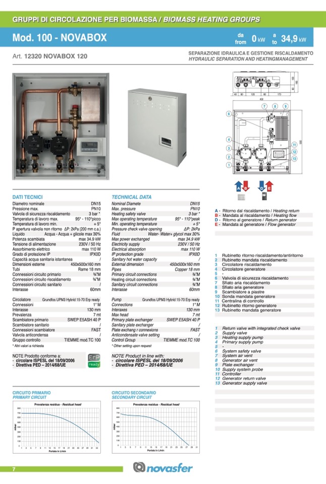
6 Valvola di sicurezza riscaldamento
7 Sfiato aria riscaldamento
Dimensioni esterne
Tubi
Connessioni circuito primario
Connessioni circuito riscaldamento
Connessioni circuito sanitario
Pipes
Primary circuit connections
Heating circuit connections
Sanitary circuit connections
Rubinetto ritorno riscaldamento/antiritorno
Rubinetto mandata riscaldamento
Circolatore riscaldamento
Circolatore generatore
Circolatore
Connessioni
Interasse
Prevalenza
Scambiatore primario
Scambiatore sanitario
Connessioni scambiatore
Valvola anticondensa
Gruppo controllo
Pump
Connections
Interaxes
Max head
Primary plate exchanger
Sanitary plate exchanger
Plate exchang r connexions
Anticondensate valve setting
Control Group
8 Sfiato aria generatore
9 Scambiatore a piastre
10 Sonda mandata generatore
11 Centralina di controllo
12 Rubinetto ritorno generatore
13 Rubinetto mandata generatore
* Altri valori a richiesta
NOTE Prodotto conforme a:
* Other setting upon request
NOTE Product in line with:
5-
6 System safety valve
7 System air vent
8 Generator air vent
9 Plate exchanger
10 Supply system probe
11 Controller
12 Generator return valve
13 Generator supply valve
Grundfos UPM3 Hybrid 15-70 Erp ready
1“ M
130 mm
7 mt
SWEP E5ASH 40 P
/
FAST
/
TIEMME mod.TC 100
Grundfos UPM3 Hybrid 15-70 Erp ready
- circolare ISPESL del 18/09/2006
- Direttiva PED – 2014/68/UE
- circolare ISPESL del 18/09/2006
- Direttiva PED – 2014/68/UE
CIRCUITO SECONDARIO
CIRCUITO PRIMARIO
PRIMARY CIRCUIT
SECONDARY CIRCUIT
7
800
700
600
500
400
300
200
100
0
Prevalenza residua - Residual head
1 3 5 7 9 11 13 15 17 19 21 23 25 27 29 31 33
800
700
600
500
400
300
200
100
0
Prevalenza residua - Residual head
1 3
5
7
9 11 13 15 17 19 21 23 25 27 29 31
Portata in L/min
Portata in L/min
PN10
3 bar *
95° - 110°picco
A -
B -
D -
E-
Mandata al riscaldamento / Heating flow
Ritorno al generatore / Return generator
Mandata al generatore / Flow generator
DN15
+ 5°
PN10
3 bar *
95° - 110°peak
+ 5°
ΔP: 2kPa
Max power exchanged
Electricity supply
Electrical absorption
IP protection grade
Sanitary hot water capacity
External dimension
1“ M
130 mm
7 mt
SWEP E5ASH 40 P
/
FAST
/
TIEMME mod.TC 100
1 Return valve with integrated check valve
2 Supply valve
3 Heating supply pump
4 Primary supply pump
17
ktWo
SEPARAZIONE IDRAULICA E GESTIONE RISCALDAMENTO
40 60
120
60
170
450
47
kW
HYDRAULIC SEPARATION AND HEATINGMANAGEMENT
6
4
3
2
1
7
8
9
11
12
13
from
from
to
a
m
b
a
r
m
b
a
r
5
0
0
6
0
1
6
0
1
0
0

