4.0 Jointing Instructions
4.1 Sizes 6 to 54 mm
All installations must be completed in line with local
regulations and by-laws governing the installation, and
all applicable health and safety practices must be
adhered to.
4.2 Minimum distances and insertion depths
Table 5:
4.3 Threaded joints for water applications
The use of a drinking water listed sealant or tape (e.g.
PTFE) is recommended for making joints on fittings
with taper male threads. For making joints with parallel
connector threads, a good quality washer should be used
to suit the particular application. Suitable drinking water
approved washers are supplied with Conex Compression
tap connector fittings and these should be used.
4.4 Connecting to plastic pipes
When joining soft copper tube to EN 1057-R220 or plastic
pipes to BS 7291, EN 15875 and EN 15876, it is essential
that an appropriate tube liner is also fitted. A Conex
Compression joint makes a metal to metal seal which
normally eliminates the need for jointing compounds and
sealants. On larger sizes, particularly 54 mm, it may be
necessary to use an additional WRAS approved sealant.
Jointing instructions, when using sealant, are available
from our technical department, technical@ibpgroup.com.
Table 6: Spanner size for compression nut
Tube
dimension
Minimum
distance
Minimum tube
length
Insertion
depth
A
L
E
mm
6
14
46
16
8
15
49
17
10
15
51
18
12
16
56
20
15
16
58
21
16
17
61
22
18
17
65
24
20
17
65
24
22
17
67
25
28
17
69
26
35
19
81
31
42
21
85
34
54
24
106
41
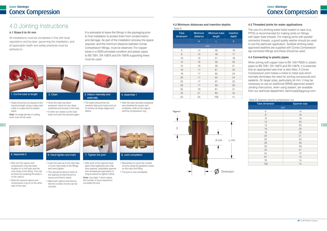
It is advisable to leave the fittings in the packaging prior
to final installation to protect them from contamination
and damage. As part of the installation process the space
required, and the minimum distance between Conex
Compression fittings, must be observed. For copper
tubes in a R220 annealed condition and plastic pipes
to BS 7291, EN 15875 and EN 15876 supporting liners
must be used.
1. Cut the tube to length
2. Clean
3. Deburr internally and
externally
4. Assemble 1
Tube dimension
Spanner size
mm
6
14
8
16
10
18
12
20
15
25
16
26
18
28
20
31
22
33
28
39
35
48
42
57
54
72
67
15
76
15
108
15
• Tubes should be cut square to the
required length using a rotary tube
cutter or a pipe slice for plastic
pipes.
Note: An angle grinder or cutting
torch must not be used.
• Once the tube has been
prepared, check for any deep
scratches and scores in the tube.
• If either are visible cut the tube
back and start the process again.
• The tubes should then be
carefully deburred inside and out
to remove all sharp edges and
debris.
• After the tube has been prepared
and checked for scores and
scratches, slide on the capnut
and the compression ring.
Figure 2
8
9
5. Assemble 2
6. Hand tighten and mark
7. Tighten the joint
8. Joint completion
• After the first capnut and
compression ring has been
located on to the tube add the
main body of the fitting. This can
be done by screwing the body in
to the capnut.
• Slide the second capnut and
compression ring on to the other
side of the tube.
• Insert the tube up to the tube stop
in to the main body of the fittings
and hand tighten.
• This should be done on both of
the capnuts so that the joint is
secure and fixed in place.
• Mark each capnut and tube so
that the number of turns can be
counted.
• After both of the capnuts have
been hand tightened use a flat
face spanner, adjustable spanner
(not serrated jaw type pliers) or
torque wrench to tighten further.
Note: Use table 7 which states
the number of turns required to
complete the joint.
• Remember to count the number
of turns using the guidance marks
on the tube and fitting.
• The joint is now completed.
A min
L min
Dimension
E

