DN
A
F
C
n x D
C1
n1 x D1
32
40
50
65
80
100
125
150 200 250 300 350 400 450 500 600
93
93
99
108
116
129
142
156
177
206
217
266
266
200
200
250
140
150
165
185
200
220
250
285
340
405
460
520
580
640
715
840
n°x D
n°x D
n1x D1
n°x D
4
2
13
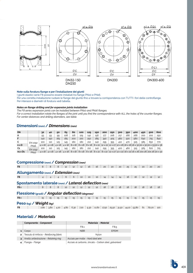
Note sulla foratura flange e per l’installazione dei giunti
I giunti elastici serie F8 possono essere installati tra flange PN10 e PN16.
Per una corretta installazione ruotare le
flange del giunto fino a trovare la corrispondenza con TUTTI i fori delle controflange.
Per interassi e diametri di foratura vedi tabella.
Notes on flange drilling and for expansion joints installation
The F8 series expansion joints can be installed between PN10 and PN16 flanges.
For a correct installation rotate the flanges of the joint until you find the correspondence with ALL the holes of the counter flanges.
For center distances and drilling diameters, see table.
Dimensioni
(mm)
/ Dimensions
(mm)
4213
C1
A
A
C
F
C
C
F
F
F
DN32-150
DN200
DN300-600
DN250
EN 1092
PN16
EN 1092
PN10
100
4 x 18
100
4 x 18
110
4 x 18
110
4 x 18
125
4 x 18
125
4 x 18
145
160
180
210
240
295
355
410
470
525
585
650
770
12 x 27 12 x 26 16 x 26 16 x 30 20 x 30 20 x 33 20 x 36
355
400
460
515
565
620
725
12 x 27 12 x 22 16 x 22 16 x 26 20x 26 20x 26 20 x 30
2176
5
4 x 18
145
4 x 18
8 x 18 8 x 18 8 x 18 8 x 22 12 x 22
Cat2016_F8_sezdim+mat
A160 180 210 240 295
rev. 9/06/2017
8 x 18 8 x 18 8 x 18 8 x 22 8 x 22
Compressione
(mm)
/ Compression
(mm)
F8
8
8
8
12
12
12
16
16
20
20
20
25
25
20
20
20
Allungamento
(mm)
/ Extension
(mm)
F8
4
4
4
6
6
10
10
10
14
14
14
16
16
12
12
12
Spostamento laterale
(mm)
/ Lateral deflection
(mm)
F8 ±
8
8
8
10
10
12
12
12
18
18
18
18
18
18
18
18
Flessione
(gradi)
/ Angular deflection
(degrees)
F8 ±
15
15
15
15
15
15
15
15
15
15
15
15
15
15
15
15
Peso
(kg)
/ Weight
(kg)
F8
2,80 3,80 4,20 4,80 6,30
7,20
9,30 11,60 17,50 25,50 31,50 44,10 53,80
61
82,20 120
Materiali / Materials
Componente - Component
1 Corpo
2 Tessuto di rinforzo - Reinforcing fabric
3 Anello antiestrazione - Retaining ring
4 Flangia - Flange
Cat2016_F8-T8_p3.drw1_sezdim+mat
Materiale - Material
rev. 02/05/17
F8.1
F8.5
NBR
EPDM
Nylon
Acciaio per molle - Hard steel wire
Acciaio al carbonio, zincato - Carbon steel, galvanised
www.brandonivalves.it
431
V
A
L
V
E
S
A
r
t
.
T
8
T
P
A
r
t
.
F
8
D
N
D
N
F

