Campo regolazione
portata massima
[m
3
/h]
–
–
–
–
0,03-15
0,05-120
0,1-250
6-380
–
–
–
–
6-380
0,015-15
2,2-420
Kvs
[m
3
/h]
1,0-1,6
0,4-25
4,0-400
125-630
4,0-160
–
–
4,0-400
4,0-400
4,0-400
125-630
–
–
Max Δpv
[bar]
4,5
12-20
10-20
10-20
15-20
10-20
10-20
10-20
20
10-20
Temperatura
max.
[°C]
120
150
150
3)
150
3)
150
150
3)
150
3)
150
3)
150
150
3)
150
3)
350
3)
Opzioni d montaggio
1)
Uso raccomandato
Ritorno
Mandata e ritorno
Mandata e ritorno
ü
Mandata e ritorno
ü
Ritorno
Ritorno
ü
Mandata e ritorno
ü
Bypass
Bypass
ü
Bypass
ü
RETE DI
DISTRIBUZIONE
ü
ü
ü
ü
ü
ü
ü
SOTTOSTAZIONE
UTENTE
ü
ü
ü
ü
1,6-25
12-20
ü
ü
ü
0,03-15
–
12-20
10-20
150
Mandata e ritorno
Mandata e ritorno
ü
ü
ü
ü
ü
ü
–
4,0-25
4,0-25
12-20
16-20
150
Bypass
ü
ü
ü
ü
ü
ü
–
–
0,4-25
4,0-400
16-20
10-20
150
150
3)
Portata
Portata
ü
ü
ü
ü
ü
–
1,0-6,3
10
10-20
200
Portata
Portata
ü
ü
ü
ü
ü
0,015-15
0,1-250
0,4-25
4,0-400
12-20
10-20
10-20
150
150
3)
150
3)
Portata / ritorno
Mandata e ritorno
ü
Mandata e ritorno
ü
ü
ü
ü
ü
ü
ü
0,035-38
–
4
120
150
150
4)
Mandata e ritorno
Mandata e ritorno
Mandata e ritorno
ü
ü
ü
ü
FONTE DI ENERGIA E
RETE DI TRASPORTO
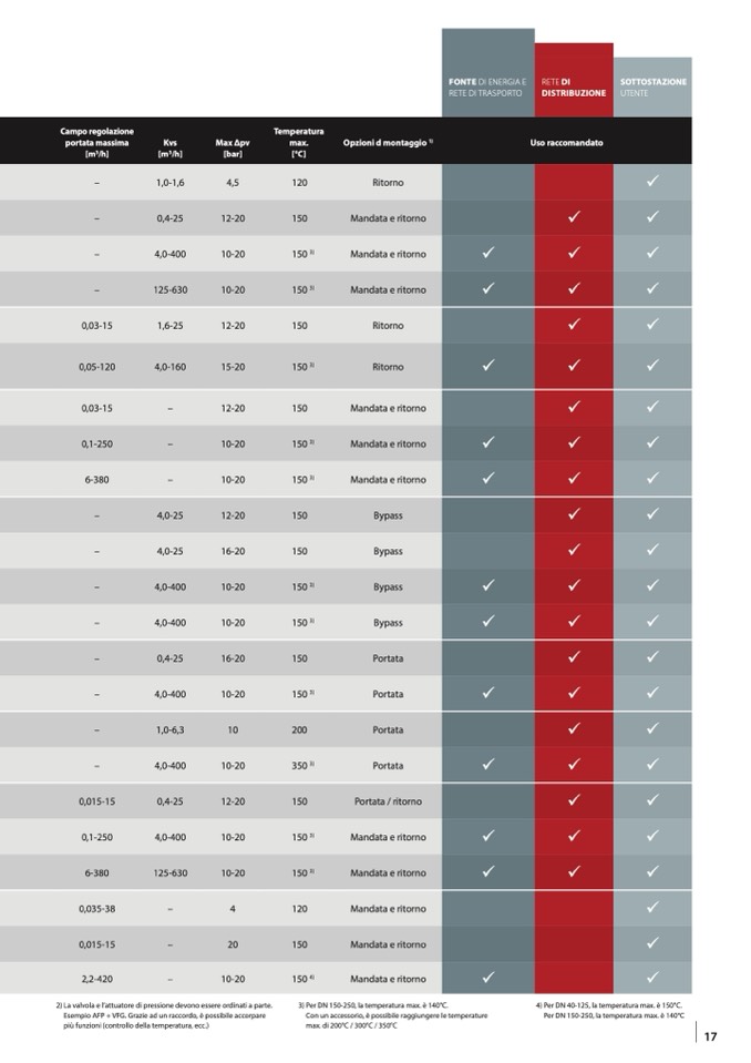
2) La valvola e l’attuatore di pressione devono essere ordinati a parte.
Esempio AFP + VFG. Grazie ad un raccordo, è possibile accorpare
più funzioni (controllo della temperatura, ecc.)
3) Per DN 150-250, la temperatura max. è 140°C.
Con un accessorio, è possibile raggiungere le temperature
max. di 200°C / 300°C / 350°C
4) Per DN 40-125, la temperatura max. è 150°C.
Per DN 150-250, la temperatura max. è 140°C
17

