FSR
Technical details
4.224
FLEXWELL® Safety Pipe
Connecting fitting GRAPA with collar and split loose flange
Compression joint, joining method: outer pipe hard solderin
g
FLEXWELL® Safety Pipe
with compression-type graphite seal inner pipe and hard soldering outer pipe
,
pressure stage PN 1
0
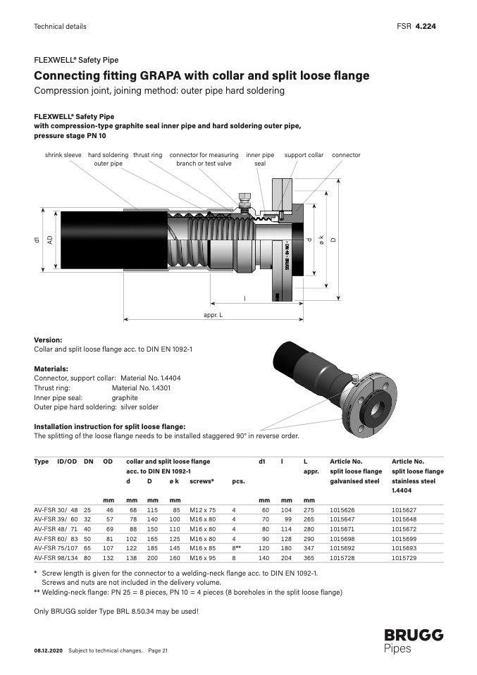
shrink sleeve hard solderin
g
outer pipe
thrust rin
g
connector for measurin
g
branch or test valve
inner pipe
sea
l
support collar connector
d
1
A
D
d
ø
k
D
l
appr.
L
Version:
Collar and split loose flange acc. to DIN EN 1092-1
Materials:
Connector, support collar:
Material No. 1.440
4
Thrust ring:
Material No. 1.4301
Inner pipe seal:
graphit
e
Outer pipe hard soldering: silver solder
Installation instruction for split loose flange
:
The splitting of the loose flange needs to be installed staggered 90° in reverse order
.
Type ID/OD DN OD
collar and split loose flange
d1
l
L
Article No.
Article No
.
acc. to DIN EN 1092-1
appr.
split loose flange split loose flang
e
d
D
ø k
screws*
pcs.
galvanised steel
stainless steel
1.440
4
mm
mm mm
mm
mm
mm
m
m
AV-FSR 30/ 48 25
46
68 115
85 M12 x 75
4
60
104
275
1015626
1015627
AV-FSR 39/ 60 32
57
78 140
100 M16 x 80
4
70
99
265
1015647
1015648
AV-FSR 48/ 71 40
69
88 150
110 M16 x 80
4
80
114
280
1015671
1015672
AV-FSR 60/ 83 50
81
102 165
125 M16 x 80
4
90
128
290
1015698
1015699
AV-FSR 75/107 65
107
122 185
145 M16 x 85
8**
120
180
347
1015692
1015693
AV-FSR 98/134 80
132
138 200
160 M16 x 95
8
140
204
365
1015728
1015729
*
**
Screw length is given for the connector to a welding-neck flange acc. to DIN EN 1092-1
.
Screws and nuts are not included in the delivery volume
.
Welding-neck flange: PN 25 = 8 pieces, PN 10 = 4 pieces (8 boreholes in the split loose flange
)
Only BRUGG solder Type BRL 8.50.34 may be used
!
08.12.2020 Subject to technical changes. Page 21

